MINI SEAL 110
Parts List and
Servicing Instructions
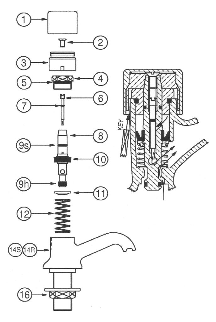
PARTS LIST
1H. CAP hot
1C. CAP cold
2. SCREW
3. INNER CAP
4. HEAD
5. SEAL RING
6. REGULATING SCREW
7. SEAL RING
8. SPINDLE
9S. SEAL RING (soft)
9H. SEAL RING (hard)
10. ‘U’ SEAL
11. SPRING WASHER
12. SPRING
14R or 14S BODY
16. BACK NUT
Parts 1 to 12 are available as individual items.
We can also supply the following pre assembled units:
110/4-11 Spindle Assembly with Head
110/6-11 Spindle Assembly
110/Seal Kit – comprising seals 5, 9S, 9H and 10
When ordering parts, please quote the valve number and then the item number. For example 110/10 for the ‘U’ Seal or 110/4-11 for the Spindle Assembly with Head.
Note that Seal Ring 110/7 is only supplied fitted to the Regulating Screw 110/6.
TO REMOVE LOCKABLE CAP
- Keep supply turned on.
- With the 1/8” square key (provided with the valve) inserted in a groove at the rear of the Body, rotate Cap (1) until the Inner Cap (3) engages with the key.
- Push key firmly up under Cap (1) and unscrew Cap (1) anti-clockwise.
- Remove Screw (2) and pull Inner Cap (3) from Spindle (8).
TO REMOVE FOREIGN DEBRIS FROM THE VALVE
If the valve starts to run continuously then it is possible that some foreign debris has fouled it. In many cases this quick and simple procedure will allow the debris to be cleared: –
- Remove Cap (1) and Screw (2) as detailed above.
- Insert a 3mm wide straight bladed screwdriver through the hole in the Spindle (8) and engage the Regulating Screw (6). Unscrew and remove the Regulating Screw. Take care as a small amount of water may be discharged from the Spindle when the Regulating Screw is removed.
- Operate the valve a couple of times by pushing the Spindle down until its end is flush with the Head (4). Do not push the spindle any further inwards. Again take care, as a small quantity of water will be discharged through the centre of the Spindle. This will help to flush out the debris that may be causing the blockage.
- Examine the ‘V’ groove in the end of the Regulating Screw and ensure that it is clear of debris.
- Refit the Regulating Screw into the Spindle and lightly screw fully home. Again operate the valve by pushing the Spindle inwards until its end is flush with the Head. Unscrew the Regulating Screw until the valve closes just slowly enough to prevent concussion in the supply pipe.
- Refit the Inner Cap and Screw. With the square key retaining the Inner Cap (3), fit and tighten the Cap (1).
TO ADJUST AGAINST CONCUSSION
- Keep water supply on.
- Remove locable Cap (1) and screw (2) as detailed above.
- Insert a 3mm wide straight bladed screwdriver through the hole in the Spindle (8) and engage the Regulating Screw (6). Unscrew about 3 or 4 turns and operate the valve several times to clear air and foreign matter, which may have accumulated, from the Regulating Screw seating.
- Lightly screw the Regulating Screw fully clockwise. Operate the valve. Unscrew the Regulating Screw until the valve closes just slowly enough to prevent concussion in the supply pipe.
Note that this fitting is not designed as a time delay valve and as such the Regulating Screw should only be set to prevent concussion and no other delaying action to the valves closure.
IF THE REGULATING SCREW IS SCREWED DOWN TOO FAR,
OR BLOCKED, THE VALVE WILL DISCHARGE CONTINUOUSLY.
TO DISMANTLE FOR RE-WASHERING
- Turn off water supplies.
- Remove the lockable Cap (1), Screw (2) and Inner Cap (3) as detailed above.
- Unscrew the Head (4). Pull the Spindle (8) from the Body (14) while easing with a circular motion to the spindle.
- Unscrew the Regulating Screw (6) from the Spindle and ensure that the ‘V’ groove and Spindle are clear of debris.
- Replace seals if required, taking care to avoid scratching the locating grooves by using a non-metallic implement.
RE ASSEMBLY
Re assembly is the reverse of the above dismantling procedure but with the following additions: –
- Ensure that the valve is properly assembled and the Head is firmly secured.
- Turn the water supply on and adjust against concussion as detailed above.
- Re fit the Inner Cap (3) and Screw (2), then with the square key stopping the Inner Cap (3) from rotating, fit and tighten the locable Cap (1).